
★This column is a commentary on lost wax casting with a block molding method
This column has been presented by Yoshida Cast
The definitions of gate sprue and ingate slightly depending on sand casting method, lost wax ceramic shell method, block molding method, etc.
The term "runner sprue" originally refers to path of the molten metal to product part of a casting mold, and refers to the entire wax tree, excluding a pouring (inlet).
"ingate" that we dare to describe here is defined as the junction between gate sprue and a product.
[toc]
Place for attaching gate sprues
fundamental idea for installing gate sprues to products is to attach them at thickest area of the products in order to secure directive solidification.
The thickness of gate sprues is thickness at which gate sprues solidify later than a cast (product) part with respect to the wall thickness of the product part. The ideal thickness should be basically the same as the wall thickness of a cast (product) or 2/3 at least.
To avoid causing casting defects, the following 3 basic conditions should be secured.
| ESSENTIAL CONDITIONS FOR GATE SPRUE | ||
| 1 | Being able to supply melting metal in short time | Prevention of temperature drop down |
| 2 | Being able to cast quietly | Prevention of turbulence |
| 3 | Being able to supply melting metal until solidification of casts (products) is completed | Ensuring directive solidification |
Appropriate thickness for gate sprue and ingate
Appropriate thickness of ingate is explained using examples of jewelry ring shape.
Even if the casting temperature is appropriate, if thickness of gate sprue (ingate) is thinner or longer than that of the cast (product) part, the temperature will drop by the time the molten metal reaches the product part and this will create casting defects such as dendrite porosities.
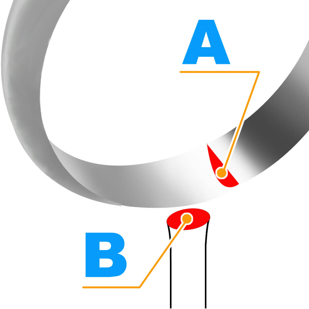
Taking a jewelry ring (annular shape) as an example, an ideal ingate is as thick as the arm of the ring.
Let cross-sectional area is “A” and cross-sectional area of ingate is “B”. thickness of the ingate should be determined within the range of A: B = 1: 1 to 1: 2/3.
For thicknesses in this range, the length of the gate sprue should be about 1 cm (approx. 2/5 inch) from a center sprue.
Attaching with a thinner or longer sprue will make probability of shrinkage cavities increase, as additional melting metal cannot be replenished for metal shrinkage during solidification.
In some cases, a large cavity may occur inside of a product around ingate area.

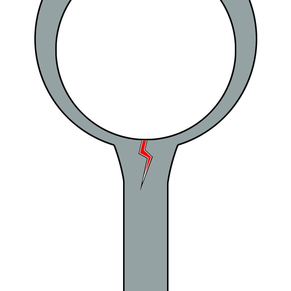
If a thicker or shorter ingate is attached, molten metal in the gate sprue will coagulate too slowly, and stress of solidification shrinkage around the ingate area may cause cracks from ingate to the cast (product).
Even if thickness of ingate is appropriate, cracks may occur depending on the shape of product.
In that case, attach a thin rod of about φ1 mm (diameter 0.04 in) × 5 mm L (0.2 in. length) or a plate of about 0.2 mm T (0.008 in. thickness) to the ingate to accelerate the solidification speed of ingate to prevent cracking problems.
Measures to prevent "cracking" at the joint part between ingate and product
The methods to prevent "cracking" at the joint part between ingate and product are summarized as below.
| Preventive Measures for Cracking | |
| 1 | To expel internal gas being in casting metal |
| 2 | Do not unnecessarily raise temperature melting metal too much when casting |
| 3 | Let cast molten metal solidifies in the order of “farthest area of product from ingate” → “product part close to ingate” → “ingate” → ”gate sprue” → “Center Sprue” → “Head (Button)”. |
| 4 | To secure appropriate air permeability of molds (investment powder) |
| 5 | Thickness of ingate and gate sprue should not be thicker than thickness of product at the joint part. |
| 6 | Casting molds should be completely de-waxed and burn out in order to terminate carbide and residuum |
| 7 | In case of pressure casting, speed for pressure supply should be slower |
| 8 | In case of centrifugal casting, adjust rotation speed appropriately slower |
If cracks occur even measures 1 to 8 are followed, take measures to increase the cooling rate of ingate.
① Attach a rod of about φ1mm (0.04 in diameter) x 5mmL (0.2 in. length) / at ingate area
② Attach a thin plate of about 3 mm 0.3 mm (0.01- 0.02 in.) x 7 mm (0.2-0.3 in.) x 0.3 mmT (0.01 in. thickness) between ingate and product.


Appropriate mounting place of gate sprues
Attach a gate sprue at the place where the molten metal solidifies last, that is, in the thickest part of a product.
Let’s take an example with a signet ring. In this case, basically, one sprue is attached
If a gate sprue is attached at thin place, molten metal in the gate sprue will solidify before product completely does.
In this case, sufficient melting metal that is necessary to be fed to cover shrinkage cannot be supplied at the time thicker part solidifies.
As a matter of result, shrinkage porosities will occur.
It is important to coagulate in order from farthest from attached gate sprue to coagulate the gate sprue.
For rod-shaped products, attaching a gate sprue straight to the rod body may sometimes causes defects.
In this case, if the gate sprue is attached with slight angle, the defect may be settled.


A shape that requires gate sprue to be divided into multiple
Depending on product shape, multiple pieces are required to be attached to a cast (product).
On the other hand, if there are too many sprues, turbulence will occur.
Thus, number of sprues should be determined in consideration of t flow of melting metal.
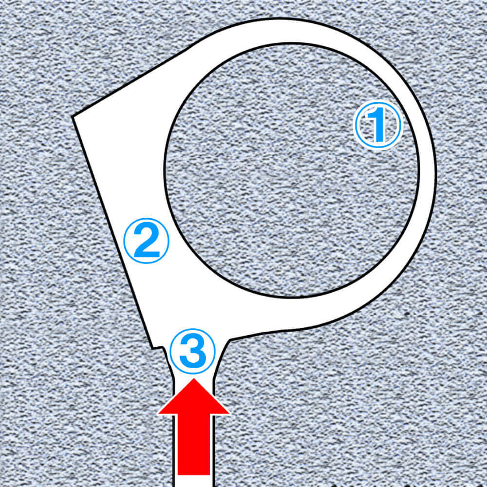
Let's take a U-shaped object as an example. The figure below shows where casting defects can occur if only one gate sprue is attached.

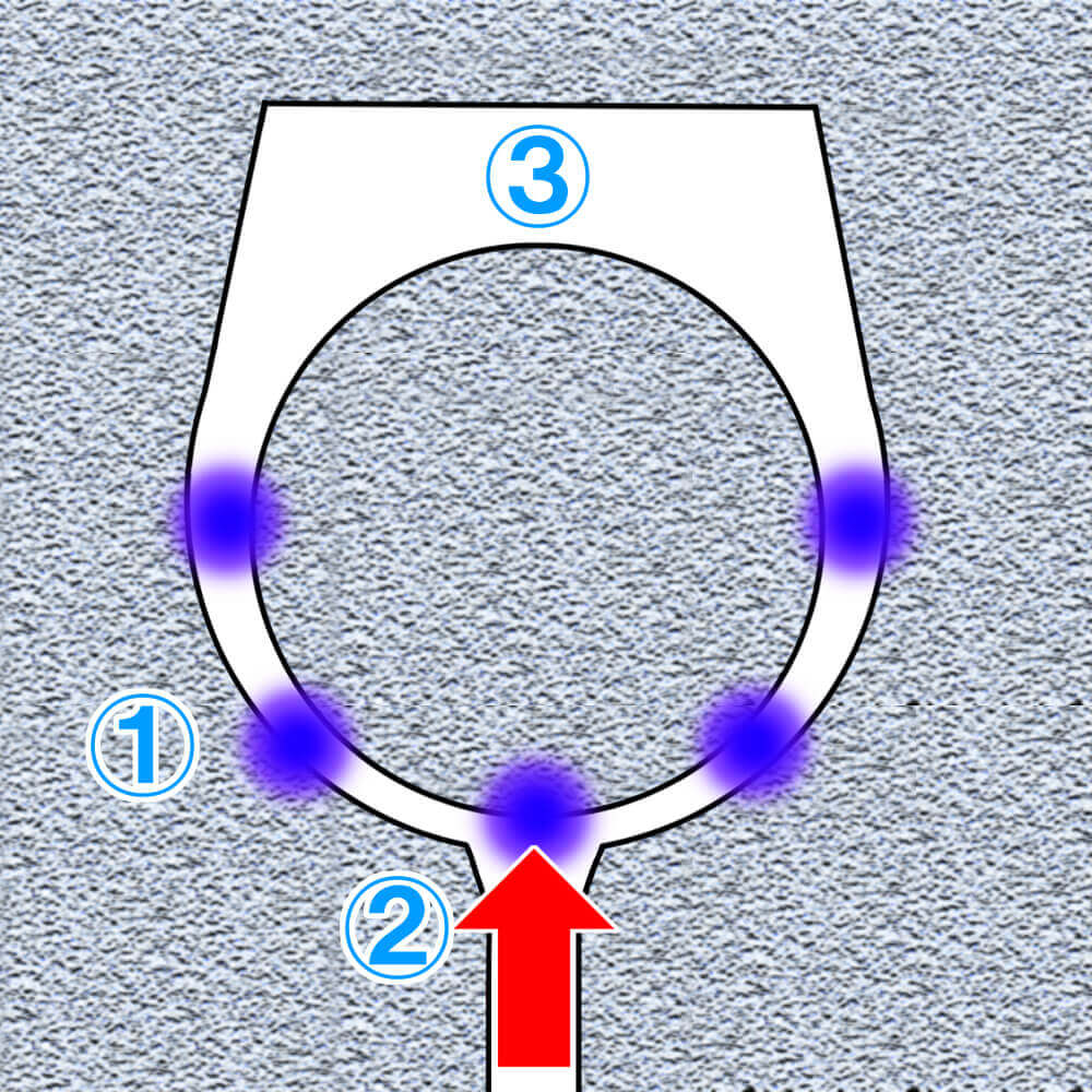
Even if the tip of gate sprue is Y-shaped, if both Y-shaped gate sprues have the same thickness or diameter, turbulence is likely to occur.
There is likely to create gas porosities or/and turbulence (roll-in) porosities due to gas entrainment in the places shown in the figure below.


To solve this problem, change the thickness of one of the Y-shaped tips of sprue to give direction to flow of melting metal.
This is an effective way to reduce collisions between two metal flow, which is one of the causes of casting defects due to turbulence.


When dividing one gate sprue into multiple lines, it is important to ensure the total area of the cross-sectional for the stem should be the same as total area of branches so that sufficient melting metal can be supplied to each branch line.
Runner sprue
What is a runner sprue?
Depending on the shape of product part, a single gate sprue may not be able to secure directive solidification or/and supply of cast metal itself may be insufficient that resulting misruns.
In this case, runners that branch off from the main gate sprue so that the melting metal can be sufficiently supplied in a short time.
If a product has a shape in which thick places and thin or thin places alternate in a product, a runner sprue(s) should be attached to each thick part(s).

There is a case a single gate sprue obviously cannot supply sufficient cast metal to fill up entire cavity.
In such a case, runner sprue preferably be attached to a place where supply for melting metal may be likely to be insufficient.

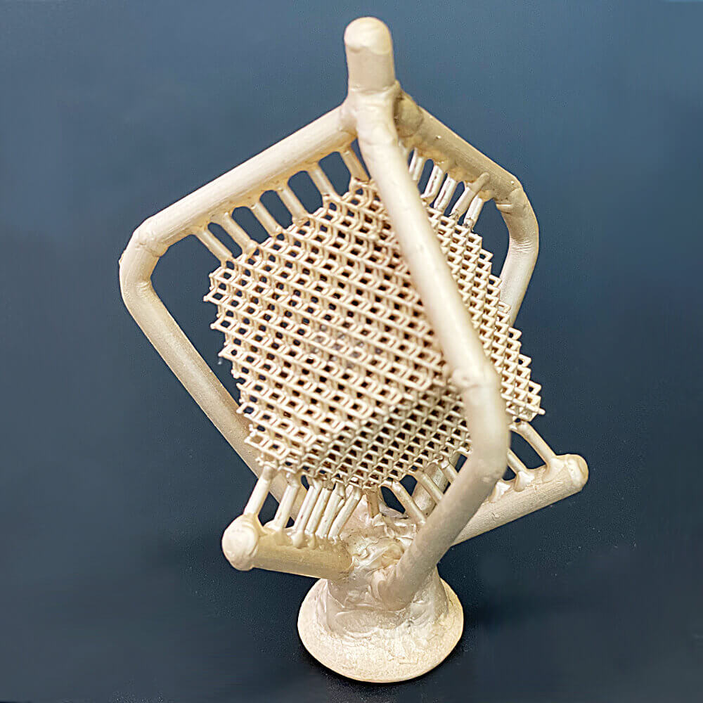
The photo shown below is a cast tree made of beryllium copper with castable resin from SLA system 3D printer.
The photo shown below is a cast tree made of beryllium copper.
The wax tree is made by SLA system 3D printer with castable resin.
Author : M.Yoshida