
★This column is a commentary on lost wax casting with a block molding method
This column has been presented by Yoshida Cast
Generally, a gas vent is a hole or outlet through which a liquid or gas can be removed or entered.
In casting, it is installed for purpose of releasing exhaust pressure in a mold.
On the other hand, if gas vents that does not suit conditions is installed, the effect may be halved, or it may cause casting defects such as shrinkage porosities.
This chapter, how to properly install gas vents for effective air exhausting and back pressure releasing are introduced.
[toc]
Reasons for installing gas vents
During casting, molten metal is subject to exhaust pressure resistance of gas inside a casting mold.
But since casting molds are made of fine particle embedding material and is breathable, gas is discharged to outside through a casting mold.
While metal is melting, molten metal pushes through this exhaust pressure resistance and fills cavities inside a casting mold.
However, if the gas cannot be discharged completely due to "casting back-pressure", "viscosity of molten metal", "shape of cavity", "amount of gas in casting alloys", and etc., it will cause casting defects such as gas porosities and dents.
Gas vents are required to prevent those casting defects.
Proper thickness and mounting location of gas vents
Thickness of gas vents should be varied depending on purpose.
When installing them for air exhausting or/and back pressure reduction, the standard is 1 to 1.4 mm. (0.04 - 0.05 approx.)
However, depending on the volume of a product, it may be thicker than the standard.
In addition, when installing a gas vent to prevent hot spots, a guideline is 3 to 3.5 mm (0.1 - 0.13 in), which is thicker than gas vents.
| LINE THICKNESS OF VENTS ACCORDING TO PURPOSE | |
| FOR AIR RELEASING | 1~1.4 mm (0.04 - 0.05 in) |
| FOR PREVENTING HOT SPOTS | 3~3.5 mm (0.1 - 0.13 in) |
NOTE : Those numbers above are a guide in case of casting with jewelry rings.
CAUTION : In case of gas vent is too thin, many porosities may occur near the mounting.
The places to be installed are the tip of dead ends or/and the places where molten metal will reach at the end.
However, effective location for installing gas vents may vary depending on casting method, shape of products, composition of casting alloy and etc.
Therefore, if gas vent that doesn't matches to casting method to be used, the effect may be halved, the casting efficiency may be impaired, shrinkage porosities due to locally over cooling may occur.
Installation place for gas vent is classified in two places, one for a wax tree and the other for casts (products).
Gas vents attached to wax trees
At the time of casting, gas in a casting mold exists at the tip of flowing molten metal and basically trapped at the tip of the wax tree.
After reaching the tip, part of melting metal flows into product section and part of it flows back toward a pouring (inlet).
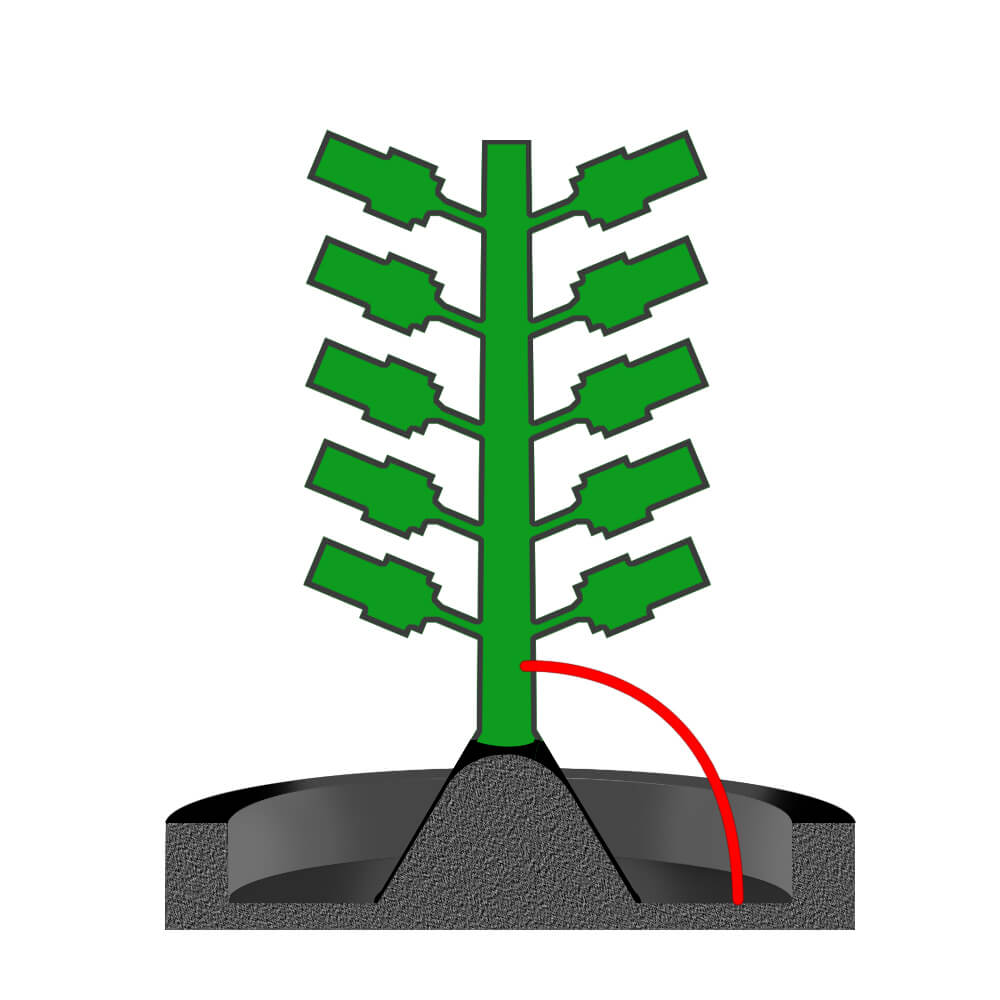
For this reason, gas in melting metal that has flowed back will stay at a point 2 to 3 cm (0.8 to 1.2 in) below a pouring (inlet / button) (Especially in case of pressure casting).
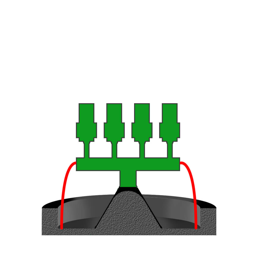
To remove this gas, install a gas vent 2 to 3 cm (0.8 to 1.2 in) above pouring part as shown in the figure below.
Install this gas vent toward pouring so that the gas can be discharged out of a casting mold.
Also, it should not be directly attached to rubber cone (button) but bottom flat area of rubber flask base.
However, there would be a risk that melting metal will leak out of a casting mold due to casting pressure.
Thus, use cautions especially with metals with a low melting temperature due to slow solidification time.
In addition, especially for metals that release a large amount of gas during solidification, it is advisable to install an extra gas sprue from the top of center sprue as shown in below figure.
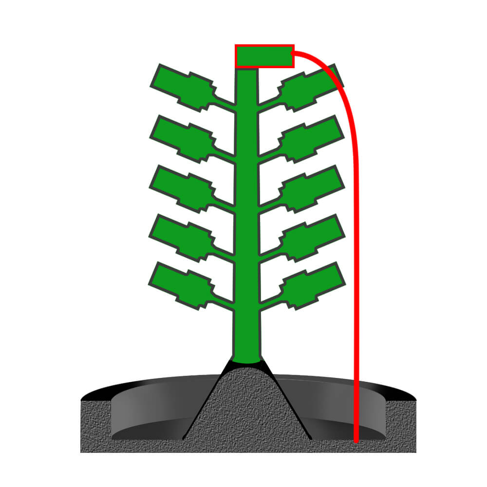
This method is especially effective for metals that are high viscous or/and have large internal gas such as stainless steel.
Also, when casting with material that tends to remain residue in a casting mold, more gas vents may be added than usual.
Gas vent in case of attaching to products
When installing a gas vent to casts (products), consider the direction of casting pressure according to a casting method to be used.
And select 1 to 4 imaginary place to put gas vent(s) with considering how molten metal flows inside a cavity of the corresponding cast (product).
| CONDITION OF THE PLACE TO ATTACH GAS VENT | |
| 1 | Where molten metal finally reaches |
| 2 | Tip at inflow direction |
| 3 | Where melting metal flows meet from two directions |
| 4 | Where melting metal finally solidifies |
If there is a part where air does not easily escape when injection wax is injected to a rubber mold, the same thing will occur in casting.
Thus, it is good to refer to state of wax patterns.
Gas vents for large volume or/and thicker casts
In case of casting with a large volume or/and thicker shape, in addition to the above things, it is necessary to consider following four things.
1. "total time consuming when melting metal fills mold cavity".
2. "direction of flow of melting metal".
3. "air permeability of a casting mold”.
4. “temperature of a casting mold".
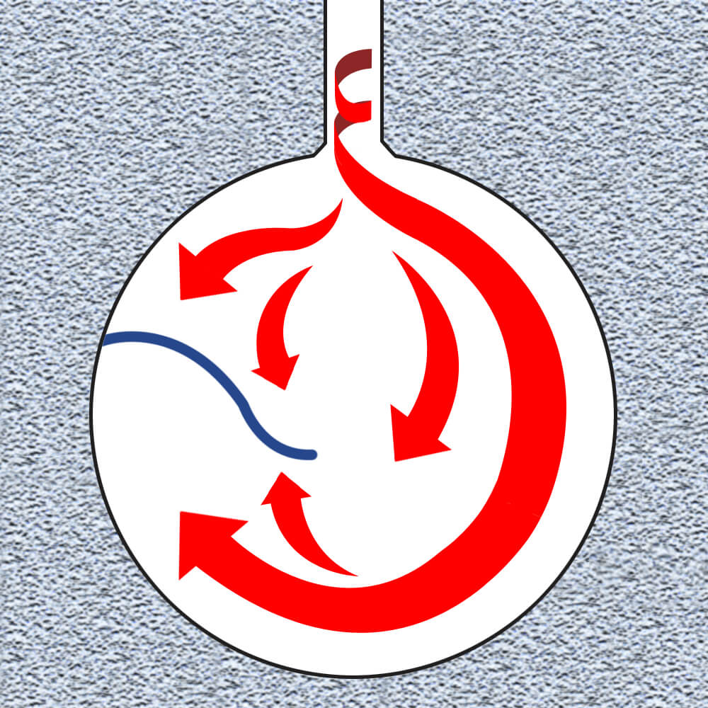
Let's take a disk-shaped object as an example to see flow of molten metal and place where gas tends to accumulate.
Melting metal that flows into product part varies depending on shape of wax tree but it basically swirls. Depending on whether it is left-handed vortex or right-handed, either the right side or the left side of the product will be filled preferentially.
Amount and flow speed of melting metal are basically large at outer periphery of the product and weaker at the center of the product than at the outer periphery.
In addition, the amount of molten metal flowing in the direction opposite to vortex of melting metal is reduced and also flowing speed is slowed down.
Therefore, both melting metals collide at around the position shown in the figure. (Blue line)
For products with such a shape, inflow direction of the molten metal can be controlled by angling gate sprue, and turbulence can be reduced.
In addition, since hot spots may be created near ingate, burn of investment powder may occur.
However, if casting metal temperature is decreased too much to prevent the burn of investment powder, flow line or/and cold shut is/are likely to occur near the blue line.
When casting with relatively metal with low melting temperature, since gas tends to collect in the place where these two streams collide, install a gas vent as shown in the figure.
When casting with metal with relatively high melting temperature, solidification time will be delayed, and gas will tend to be pushed toward ingate area.
In this case, install a gas vent near ingate.
However, if gas vent is attached closer to ingate, the cooling rate of ingate and gate sprue may increase, and then directive solidification may be hindered.
It is necessary to adjust distance between mounting position of gas vent and ingate in accordance with wall thickness of the product or to make ingate or gate sprue thicker to slow down the cooling rate.
Author : M. Yoshida